

Heavy lift engineering for safer transport and installation
2026-07-24
Every heavy lift starts long before the hook takes load. By the time a crane operator begins hoisting, most of the operation’s risk has already been created, reduced or transferred through engineering decisions made weeks or months earlier.
For offshore, maritime and energy projects, heavy lift engineering is not only about checking whether a crane can pick up an object. It connects transport design, seafastening, temporary steelwork, vessel behaviour, rigging geometry, stability, fabrication details, approval documentation and offshore execution into one controlled operation.
That wider view matters because failures and delays rarely come from one isolated calculation. They come from interface gaps: a grillage that is structurally adequate but difficult to weld, a lift point that works in the model but clashes with installation access, a centre of gravity update that arrives too late, or an MWS comment that changes the sequence just before mobilisation.
Safer transport and installation starts by treating the lift as a complete engineered system.
Heavy lift risk is created across the full route
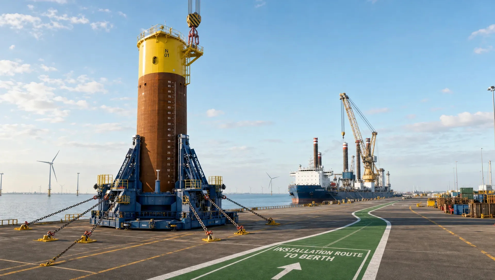
A heavy component may pass through several operational phases before it reaches its final position. It can be moved by SPMT, skidded, loaded out, transported offshore, lifted from a vessel, upended, lowered through the splash zone, landed onto supports, temporarily secured and finally integrated into a permanent structure.
Each phase changes the governing loads and constraints. A support arrangement that is acceptable during quay handling may not be sufficient for offshore transport accelerations. A lifting frame that performs well at peak load may introduce fabrication complexity or inspection access problems. A vessel deck may have enough global capacity, while local underdeck stiffening becomes the limiting factor.
This is why safe transport and installation requires early alignment between engineering, marine operations, fabrication, vessel management and approval parties. If these interfaces are not managed from the start, project teams often face late rework, additional steel, extra surveys, revised lift plans or missed weather windows.
For technical directors and project managers, the key question is not simply, “Can this be lifted?” A more useful question is, “Can this be transported, lifted, installed, approved and executed safely within the project schedule?”
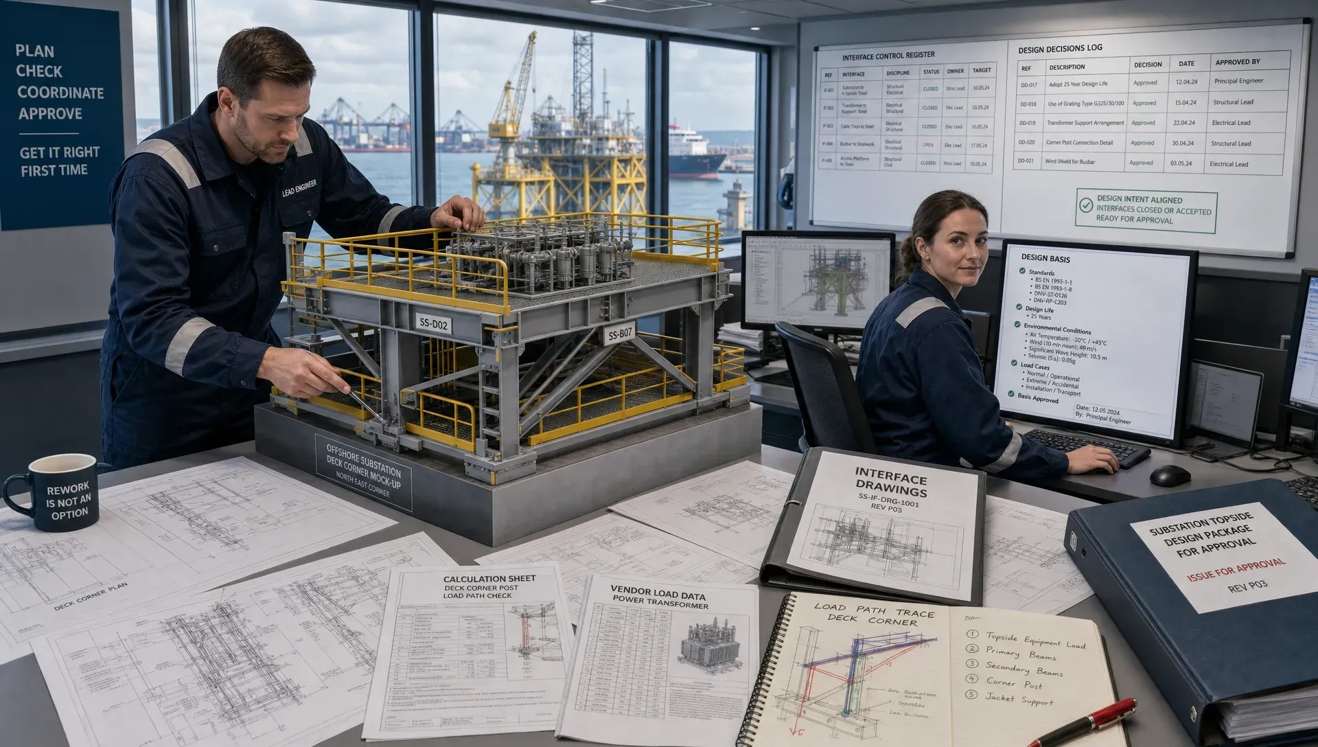
A controlled design basis is the foundation
Heavy lift design depends on reliable inputs. The design basis should define the operational envelope clearly enough that engineers, contractors, MWS reviewers and class societies are all working from the same assumptions.
Typical design basis items include component weight, centre of gravity, weight growth allowance, rigging configuration, crane data, lift radius, environmental limits, vessel motions, transport accelerations, allowable deck loads, ballast conditions, mooring assumptions, fabrication tolerances and acceptance criteria.
The challenge is that these inputs often develop during the project. Weight reports may change as the design matures. Temporary attachments may be added. Vessel availability may shift. The selected crane vessel may have different limits from the one assumed during tender. A safe engineering process therefore needs traceability, not just a single calculation snapshot.
When the design basis is controlled, engineering changes can be assessed quickly. If the centre of gravity moves, the team can identify the impact on sling loads, crane utilisation, grillage reactions and stability. If weather limits are revised, transport and installation loads can be recalculated without losing control of the documentation chain.
This approach supports the same objective described in Fusie Engineers’ article on heavy lift engineering checks that prevent offshore delays: early technical clarity reduces the risk of late-stage surprises.
Load paths must remain clear from yard to final installation
A lifted or transported structure does not care how project scopes are divided. Loads still need a continuous, justified path through every temporary and permanent interface.
During transport, vertical and horizontal loads pass from the component into saddles, grillages, seafastening, deck structure and underdeck reinforcement. During lifting, forces move through padeyes, trunnions, lifting frames, rigging, shackles, hooks and crane structure. During landing, local bearing, guide forces and impact allowances may govern temporary support design.
Good heavy lift engineering makes these load paths explicit. It avoids relying on assumptions such as “the deck is strong enough” or “the support frame will distribute the load”. Instead, it checks local and global effects, eccentricity, torsion, weld demand, fatigue sensitivity where relevant, and the practical sequence used to transfer load from one system to another.
This is especially important for offshore wind foundations, topside modules, subsea structures, vessel equipment, dredging components, bridge sections, decommissioned assets and large retrofit packages. In each case, temporary structures may experience loads that are very different from their final in-service condition.
The safest solutions are often not the heaviest ones. A well-designed load path can reduce steel use, simplify welding, improve inspection access and shorten fabrication time while still meeting strength, stability and approval requirements.
Rigging geometry and dynamic effects need practical margins
Rigging design is one of the most visible parts of a heavy lift, but it is also one of the easiest areas to underestimate. Sling angles, hook height, spreader beam stiffness, shackle orientation and lift point tolerances all influence load distribution.
Small geometry changes can create significant load differences. A slight centre of gravity offset can overload one sling. Limited headroom can force shallow sling angles and increase horizontal forces in lift points. A rigging arrangement that looks symmetrical on a general arrangement drawing may behave differently once fabrication tolerances, sling length tolerances and installation access are considered.
Dynamic effects add another layer of complexity. Offshore lifting can involve vessel motions, crane tip movement, wave-induced accelerations, wind loading, snatch effects and changing buoyancy when an object passes through the splash zone. These effects need to be translated into realistic design factors and operational limits.
Industry standards such as DNV-ST-N001 for marine operations and marine warranty are often used as part of the approval framework for marine operations. However, standards do not replace engineering judgement. They need to be applied to the actual operation, vessel, lift object, rigging arrangement and environmental conditions.
For project teams, the practical outcome should be a lift arrangement that is strong, inspectable, installable and understandable to the offshore crew. Calculations are essential, but they must lead to a method that can be executed safely on deck.
Seafastening and grillages are installation-critical structures
Seafastening and grillages are sometimes treated as temporary steelwork of secondary importance. In reality, they are central to the safety of the transport phase and can strongly influence installation readiness.
A grillage must distribute loads into the vessel structure without exceeding deck or underdeck capacity. Seafastening must resist accelerations from vessel motions and prevent sliding, uplift, overturning or local damage during transit. Both must be designed around practical fabrication, welding access, NDT requirements, coating, removal, sea fastening release and offshore workability.
Overly complex temporary steel can create schedule risk. If welds are difficult to access, fabrication takes longer. If removal requires excessive hot work offshore, execution risk increases. If underdeck reinforcement is discovered late, mobilisation can be delayed. If tolerances are too tight, loadout or fit-up can become a site problem.
Buildability is therefore a safety and schedule issue, not just a fabrication preference. The principles discussed in structural engineering choices that improve buildability offshore apply directly to heavy lift work: clear load paths, realistic weld details and practical installation sequences reduce risk before the vessel leaves port.
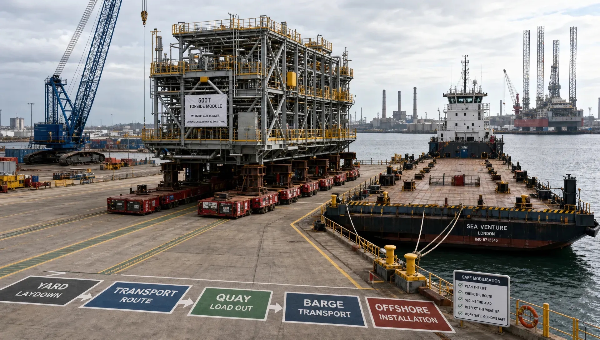
A heavy offshore component secured on a transport vessel with visible grillages, seafastening beams, lifting points and deck supports, viewed from the vessel side with the quay and harbour in the background, as engineers inspect the arrangement from the jetty before mobilisation.
Vessel constraints can define the engineering solution
A heavy lift operation is always limited by the vessel or vessels involved. Crane capacity is only one part of the picture. Deck strength, stability, ballast capability, clear deck area, underdeck framing, mooring arrangement, access routes, sea state response and equipment layout can all govern the design.
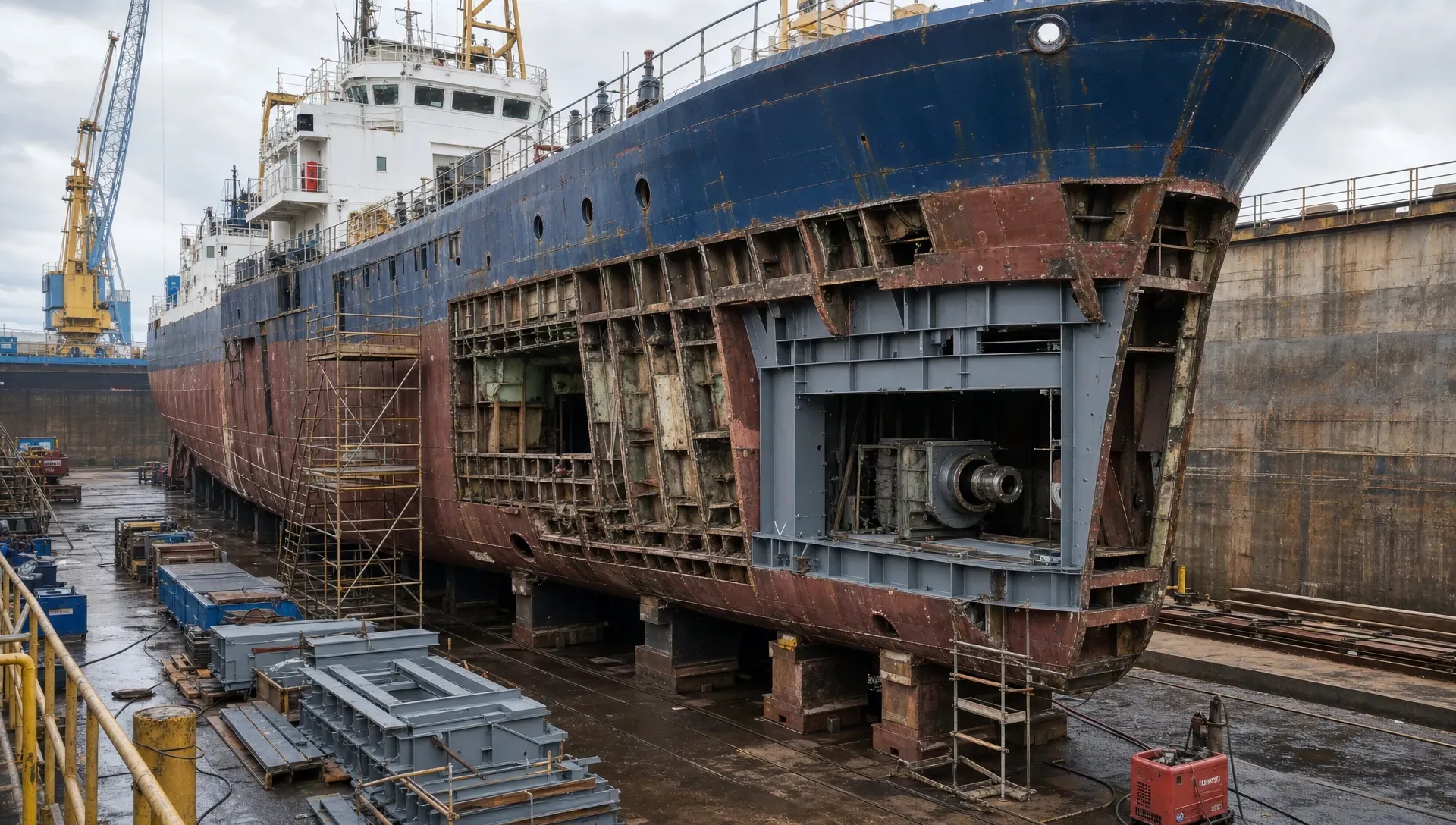
For transport vessels, allowable deck loads and underdeck structure often shape grillage position and support spacing. For crane vessels, lift radius, hook height, crane curves, ballast requirements and simultaneous operations define what is feasible. For retrofit and ship repair projects, legacy vessel data, unknown structural condition and class constraints can make the engineering scope more demanding than it first appears.
This is where coordination between naval architects, structural engineers and marine operations specialists becomes critical. A technically correct lifting frame is not enough if the vessel cannot maintain the required stability condition. A seafastening design is incomplete if it ignores deck structure below. A mooring plan may need to be considered alongside lifting limits, installation tolerances and weather downtime.
Fusie Engineers’ wider marine engineering perspective is relevant here, particularly for projects where heavy lift work connects with vessel modification, ship design, piping, retrofit or offshore execution. The company’s article on marine engineering for safe retrofit and offshore work explains how these disciplines need to work together rather than in isolation.
Approval readiness should be designed into the work, not added later
MWS and class approval can become a bottleneck when documentation is incomplete, inconsistent or delivered too late. For heavy lift operations, reviewers need to see not only final results but also the logic behind them.
Approval-ready documentation typically includes a clear design basis, calculation reports, FEM outputs where required, rigging drawings, lifting arrangements, seafastening drawings, grillage details, deck strength checks, stability information, motion or acceleration assumptions, method statements and inspection requirements.
The documents must tell one consistent technical story. If a weight differs between the lift plan and calculation report, reviewers will raise questions. If a drawing shows a weld detail that is not reflected in the calculation, fabrication and approval can diverge. If operational limits are buried in a report rather than visible in the procedure, site teams may not apply them correctly.
Good documentation is not paperwork for its own sake. It is a risk-control tool. It helps the project team prove that the operation is defined, checked, buildable and ready for execution. It also gives MWS, DNV, Lloyd’s Register, ABS or other approval bodies the information needed to review the work efficiently.
Installation engineering must account for offshore reality
Transport design gets the structure to site. Installation engineering gets it safely into position.
Offshore installation introduces uncertainties that do not exist in a workshop or fabrication yard. Vessel motions, visibility, current, wind, wave conditions, limited deck space, simultaneous operations, communication delays and emergency response constraints all affect execution.
The engineering therefore needs to define more than the maximum lift load. It should address installation tolerances, guide systems, landing aids, temporary supports, contingency positions, rigging removal, access, dropped object risks, clash checks, hold points and allowable weather conditions.
For subsea or partially submerged operations, buoyancy and hydrodynamic effects may control the critical stage. For decommissioning, unknown asset condition and changed weight distribution can become major uncertainties. For offshore wind and renewable energy projects, serial installation makes repeatability and efficient offshore handling especially important. For heavy civils and bridge works, site constraints and temporary support conditions may govern the lift just as much as crane capacity.
A strong installation engineering package gives the offshore team clear limits and practical steps. It should reduce judgement calls during critical operations, not transfer unresolved design decisions to the vessel.
Common causes of avoidable heavy lift delays
Many heavy lift delays are preventable if the right questions are asked early enough. The most common issues are not always complex analysis failures. They are often coordination, data and constructability problems.
Frequent causes include:
- Late weight or centre of gravity changes that affect rigging, crane utilisation and support reactions.
- Temporary structures that are structurally adequate but slow or difficult to fabricate.
- Missing underdeck checks for grillage or sea fastening loads.
- Drawings, calculations and method statements that use inconsistent assumptions.
- Insufficient allowance for access, rigging removal, inspection or offshore release.
- MWS comments raised late because the approval package was incomplete.
- Vessel constraints identified after the lift arrangement has already been developed.
Reducing these delays requires more than adding calculation capacity. It requires engineering judgement, interface management and a clear understanding of how design decisions affect fabrication, mobilisation and offshore execution.
How Fusie Engineers supports safer transport and installation
Fusie Engineers supports heavy lift, offshore, maritime and energy projects with a practical engineering approach that connects calculations to execution. The team brings together structural engineers, mechanical designers, heavy lift engineers and naval architects to support scopes such as lifting arrangements, seafastening, grillages, custom tools, vessel retrofits, piping, ship design, marine engineering and offshore structural design.
For clients, this integrated capability is valuable when project interfaces are tight. A lifting arrangement may need structural verification, fabrication drawings, vessel checks and approval documentation. A transport scope may require FEM calculations, deck checks, seafastening design and coordination with MWS. A retrofit may require class-aware design decisions, piping interfaces and realistic installation access.
The focus is not only on producing drawings. It is on developing safe, buildable and approval-ready solutions that reduce steel where possible, avoid unnecessary fabrication complexity, and support on-time mobilisation. That balance is important for EPC contractors, marine contractors, offshore contractors, shipyards, renewable energy developers and vessel owners working under demanding schedules.
Fusie Engineers can support projects from concept and calculation through detailed engineering, shop drawings and operational readiness, with experience across offshore wind, maritime, decommissioning, ship repair, retrofit, dredging, green tech and traditional energy scopes.
Frequently asked questions
What is heavy lift engineering? Heavy lift engineering is the technical discipline used to plan, calculate, design and document the safe lifting, transport and installation of large or high-value components. It covers rigging, lift points, temporary structures, crane utilisation, vessel effects, seafastening, stability, load paths and approval documentation.
Why is heavy lift engineering important for offshore projects? Offshore projects involve dynamic vessel motions, harsh environmental conditions, limited access, high mobilisation costs and strict approval requirements. Heavy lift engineering reduces risk by defining how loads move through the full system and by ensuring that the operation is practical, documented and reviewable before execution.
What is the difference between lifting engineering and transport engineering? Lifting engineering focuses on the hoisting operation, including rigging, lift points, crane capacity and dynamic effects. Transport engineering focuses on moving the component safely to site, including grillages, seafastening, deck strength, vessel motions and accelerations. In heavy offshore projects, both must be engineered together.
When should heavy lift engineering start? It should start as early as possible, ideally during concept or tender development. Early input helps identify vessel constraints, lift feasibility, seafastening requirements, approval risks, fabrication complexity and cost-saving opportunities before major design decisions become difficult to change.
What documents are usually needed for MWS or class review? The exact package depends on the operation, but it often includes a design basis, lift calculations, rigging drawings, seafastening and grillage calculations, FEM reports where required, deck strength checks, stability information, method statements, inspection requirements and clear operational limits.
Build safer heavy lift operations with practical engineering support
Heavy lift operations leave little room for unresolved assumptions. Safe transport and installation depend on early engineering decisions, controlled load paths, realistic vessel data, buildable temporary steelwork and approval-ready documentation.
If your project needs heavy lift, seafastening, grillage, offshore structural, marine engineering or vessel retrofit support, Fusie Engineers can help turn complex transport and installation requirements into practical engineering deliverables for review, fabrication and execution.